|
|
DEFRINGING TUTORIAL
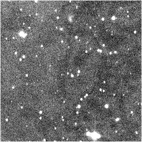
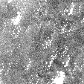
Figure 1 on the left shows an image after a strandard preprocessing: offset, dark signal subtraction and flat-field division. The analysis of the result show that the sky background is not ideally uniform. The image of right-hand side of this same figure is the addition of 8 images of the field: the phenomenon is even more visible (note that the images were not centered before the addition).
This bad uniformity of the background is caused by a phenomenon of interference fringes ("Fabry-Perot" reflections), which occur in the thickness of the detector (this one is a thinned CCD Tektronics 1024x1024 - thinning is very favorable with the phenomena, particularly visible when one works in the red and infrared part of the spectrum).
|
|
Figure 1. Part of images realised with a thinned CCD Tektronics of 1024x1024 pixels by Benoit Schillings (6 minutes integration time by images with a 30-cm telescope at F/D=9).
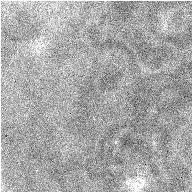
Figure 2 shows attempts to extract the image characteristic of the fringes starting from the observation images itself. On left we use the median stack. Let us suppose that the images to be treated have the generic name FIELD and that they are 8, the processing is:
SMEDIAN FIELD 8
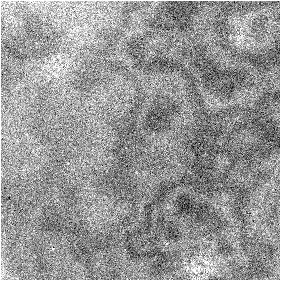
On right-hand side, we use sigma-clipping technique to eliminate stars:
COMPOSIT FIELD 1.5 10 8
In both cases the fringes are well highlighted, but there still remains some traces of brilliant stars (the transverse shift between the images of the sequence is not enough high).
|
|
Figure 2. Attempts to withdraw stars: on the left, median compositing, on the right, sigma-clipping compositing.
Command SMIN can render service in this type of situation: it determines the minimal value between the same pixels of a sequence of images. Figure 3 shows the result in the case of sequence FIELD:
SMIN FIELD 8
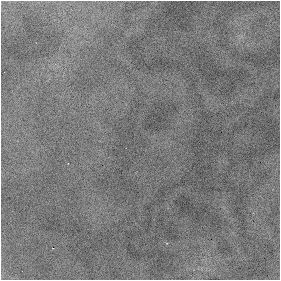
Figure 3. Image of the fringes after the use
of command SMIN.
The preprocessing of the sequence images is then supplemented by substraction of fringes map (figure 3). The complete sequence with accompanying notes is:
NOFFSET2 FIELD I 1800 8 The background of the images are standardized to 1800 (for
example)
SMIN I 8
Calculation of the
fringes map starting from the images standardized
MEDIAN3 9
Reduction of the noise by
a median filtering (optional)
SAVE FRINGE
Save the result on the disk
SUB2 I FRINGE I 0 8
Substraction of the fringes
map to the 8 images of the sequence
REGISTER I I 8
Superposition of the 8 images
ADD2 I 8
Addition of the 8 treated
images
Figure 4 shows the result after the processing above. Any trace of fringes disappeared.

Figure 4. The field after the elimination of
the fringes and the compositing of the 8 elementary images.
An alternative to SMIN command is the use of the FLAT command. For the example the procedure is:
NOFFSET2 FIELD I 1800 8 The background of the images are standardized
to 1800 (for example)
REGISTER I J 8
Superposition of the 8 images
- this is necessary for generate the file SHIFT.LST
FLAT I 2000 0 1800 3 8 Compute
the flat-field with a mean level of 1800
SAVE FRINGE
Save the result on he disk
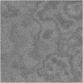
Figure 5. The fringe image produced by the
FLAT command.
|
|
|