Dither algorithm performs an optimal adding of a sequence of images as far as resolution is concerned. The principle is that, at sub-pixel level, shifts between individual input images are nearly randomly distributed. For example, a star in the first image may be centered perfectly in the middle of a pixel, whereas it will be across two pixels in the second one, and so on. Since it is easy to know the exact shift between the images, it is possible to create an output image with a finer sampling, in which resolution may be increased with respected to each input image. In fact, energy from each input pixel is dropped in the output image, and the whole processus may be compared to a drizzle.
Drizzling is adapted to undersampled images, for example when the telescope focal length is too short for the pixel size. One may consider that the system is undersampled when FWHM is smaller than 2 pixels. In this situation much of the information lost in undersample regime can be restored.
Before using drizzling technique, it is necessary to know the exact shift between the images. It is also very important that all the input images are acquired in the same conditions: same exposure time, same sky background level. If this is not the case, you have to adjust offset and gain prior applying drizzling algorithm (NGAIN and NOFFSET commands under Iris for example).
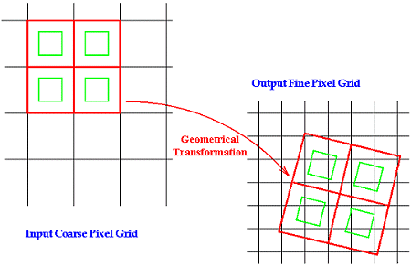
The drizzling algorithm step by step (see figure 8):
Step 1: Reduce
or coarse (by calculation !) the size of the pixels in the starting
image, but preserve the same interval between pixels.
Step 2: Project in
the final image fine grid after a geometrical transformation (take
into account if necessary shifts, rotations, optical distortions).
Step 3:
Calculate the fraction of the pixel projected in each cells of the
grid of the final image and add this fraction with the current value
with the output pixel.
Step 4: Start again at step 1 for each input image.
The "shrink" pixel size at the step 1 is crucial. We define pixfrac as the ratio of the linear size of the coarse pixel to the original input pixel linear size. If pixfrac=0 the drizzle algorithm is equivalent to interlacing, while the traditionnal shift-and-add is equivalent to pixfrac=1. One must choose a pixfrac value that is small enough to avoid degrading final image, but large enougth that then all images are dropped, the coverage of the ouput image is fairly uniform. We choose typically pixfrac between 0.5 and 0.7.

Figure
8. Schematic representation
of drizzling technique. In this particular case, the central output
pixel receives no information from the input image. It will not
be necessary the case for the following images of the sequence,
and so on. "Dark" output pixels are not a concern as long
as there are enough input frames with differents sub-pixel dither
positions to fill in the ouput image. The ratio between the input
grid size and the output grid size define the "scale factor"
parameter.

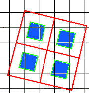
Figure 9. In blue color, area fraction of the input pixels
dropped in the output pixels.
Mathematical formulation of drizzling:
if
i = intensity of the projected input pixel
w = weight of this pixel
a = fraction of the pixel projected in a cell of the output grid
(fractional pixel overlap 0 < a < 1)
I = current intensity in the output pixel
W = current average weight in the output pixel
I' = resulting intensity in this output pixel
W' = resulting weight of this output pixel
when
W' = a . w + W
I'
= (a.i.w + I.W) / W'
The weight w of the pixel can be zero if it is a bad pixel (hot pixels, dead pixels, cosmic rays event, ...), or can be adjusted according to the local noise (the value is then inversely proportional to the variance maps of the input image).
Remenber that algorithm is effective if the images are really undersampled (FWHM of 1 to 2 pixel). The displacement, and more generaly, geometric distortion, between the individual input images must be perfectly well-known (to 1/10 of pixel precision typically). The number of input images must be large (10 or more) to avoid holes in the final image. Most important, displacement between the input images (diphering techniques) must be random on 2 axis. So, it is necessary to shift arbitrary the telescope between each exposure during deep-sky sessions. The amplitude of the shift can be of a fiew fractions of pixels in a random direction. At the processing stage the relative shifts between images is precisely determined by calculation of the centroid of stars (PSF fitting btween common stars or cross-correlation between a reference image and the input images). The registration parameters are fundamental quantities for the drizzling method.
Main performances:
1. Resolution gain can be up to 2.
2.
Combination of sequence images produce high resolution without sacrificing
the final signal to noise ratio.
3. Conservation of photometric
quality.
4. Preserve astrometric accuracy.
5. Effective
removal of the bad pixels (cosmic rays, traps, etc).
6. Optimal
compositing if the weight function is quite selected relative to
the local noise.
7. Very good geometrical correction of the
images (significant for photometry).
The Iris software implement a version of the drizzle procedure (DRIZZLE command).The algorithm was developed by Richard Hook and Andrew Fruchter to produce the The Hubble Deep Field, the deepest optical image of the universe yet taken. It is now used for many other field.
For more information about drizzle algorithm:
http://www.stsci.edu/instruments/wfpc2/Wfpc2_driz/wfpc2_driz.html
http://www.stsci.edu/~fruchter/dipher/dipher.html
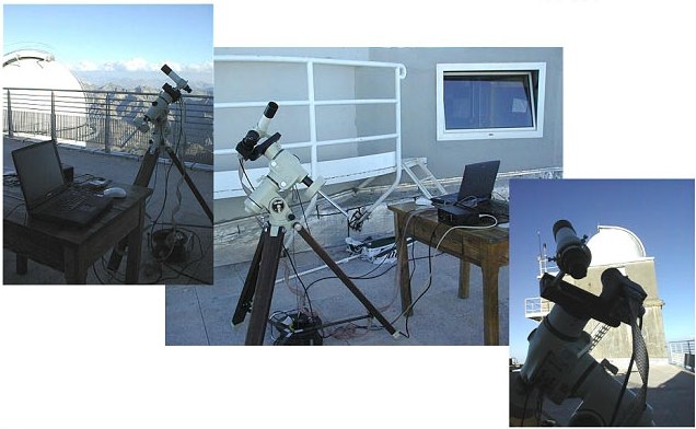
To show the effectiveness of resolution improvement by combining undersampled multiframes we will now process diphered images carried out from the observatory Pic du Midi Observatory (french Pyrénées) during the summer 1999. The instruments used are simple photographic objectives (55 to 80 mm focal lenght) and an Audine CCD camera.

Figure 10. The Audine camera installed on a Takahashi EM200 german equatorial mount at the Pic du Midi Observatory.