New features of version 3.54 (November 16, 2001)
For users of the Audine camera it is now possible to acquire images with the 32-bits operating systems Windows NT / 2000 / XP. Click here for more details.
Command COMPUTE_TRICHRO1
This command carries out the automatic processing of tri-colors images of planets. It connects commands BESTOF, SELECT, PREGISTER and ADD_NORM, this for the three colors channels. At the end of the processing the trichromatic image appears on the screen (you can then save it on the disc with command SAVEBMP or adjust its chromatic balance with the command White balance... from menu View for example). For details about planetary processing click here.
Moreover, several sequences of images are created on the hard disk. The sequence @r1, @r2.... @rn (n is the total number of image treated) contains the registered images of the red color channel and sorted by order of decreasing spacial resolution. The sequences @g1, @g2... @gn and @b1, @b2... @@bn contain same information for the green and blue channels.
COMPUTE_TRICHRO1 also automatically produces the 3 images @r, @g, @b (without indices) which represent the addition of the best n' images for the 3 colors channel (n' parameters being provided by the operator).
Command COMPUTE_TRICHRO1 using function PREGISTER to carry out the registration of the images (centering of the images of a sequence compared to the first image of this sequence), it is rather intended for the images being able not to have a contour of revolution, the such planet Saturn or lunar surface. Moreover, the use of PREGISTER imposes that the operator enters in parameter of COMPUTE_TRICHRO1 the size of the window for the calculation of registration (its must be equal to a power of two because the technique used for registration is the intercorrelation in the Fourier space).
Syntax is:
COMPUTE_TRICHRO1 [MASTER] [R] [G] [B] [SIZE] [SELECT NB.] [TOTAL NB.]
[ MASTER ] is the generic name of a sequence of image from which IRIS will make sorts it better images (as command BESTOF) and will calculate the parameters of registration for the 3 colors plans. The master sequence of images must contain images well exposed posed if possible and well resolved. Generally, in the case of the use of a Webcam camera, one will choose the images corresponding to the plan of green color.
[ R ], [ G ], [ B ] is the generic names of red, green and blue channel images respectively.
[SIZE ] is the size of the zone for the calculation for registration (choose among values 128, 256, 512 for example).
[SELECT NB. ] is the number of images added during the final composite. It is a number equal or lower than the total number of image to treat . This value is dependent on the degree of turbulence. For example for a sequence of 200 input images it is not abnormal to add only 50 images with final (they will be 50 best images).
[TOTAL NB. ] is the total number of images to be treated.
Let us suppose that you extracted from a film AVI (command Conversion AVI... from File menu) or functions of Webcam acquisitions from IRIS (Webcam menu) from the sequences from 300 images whose generic names are R, V and B for respectively the plans colors red, green and blue. You make then for example:
COMPUTE_TRICHRO1 V R V B 128 40 300
The size of the window for calculation (here 128) must be higher (but not much higher, if not calculation can be very long) than the diameter of the planet disc of planet. It is necessary moreover for run the command to surround planet by a rectangle while dragging with the mouse (press left button), such as shows it the following image:
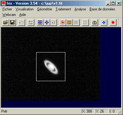
It is significant that the rectangle thus defined either centered on the center of the planetary disc. It is necessary moreover that its dimension makes it possible to include the images of planet of the beginning and at the end of the sequence. The size and the position of the selection box are less critical in the case of the lunar images (but for this type of images the three-colour process in general presents well little interest and it is by far preferable to treat monochromic images).
Calculation can be relatively long. If a problem appears in the course of processing it is always possible to stop this one while click on the stop key of the bar of tools:
![]()
Command COMPUTE_TRICHRO2
This command is very similar to COMPUTE_TRICHRO1 except the uses of function CREGISTER for the registration of the images instead of PREGISTER. Function CREGISTER determines the position of planet by adjusting a circle on the circumference of the limb. It is necessary to provide to COMPUTE_TRICHRO2 the value of the threshold of intensity from which the calculation of the circle is carried out (click here for more information). Taking into account these characteristics, it is necessary to reserve the use of this command to planets having a good symmetry of revolution (Jupiter and generally Mars).
Syntax is:
COMPUTE_TRICHRO2 [MASTER] [R] [G] [B] [SEUIL] [SELECT NB.] [TOTAL NB.]
The parameter [ THRESHOLD ] define the level of threshold which will be used to adjust a circle around planet. For example:
COMPUTE_TRICHRO2 V R V B
80 60 300
Just like for COMPUTE_TRICHRO1 you must define a selection box around planet:
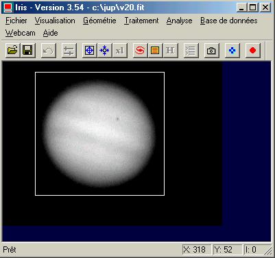
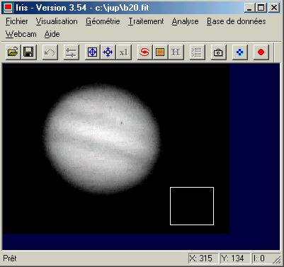
Tip: to carry out images having a good chromatic balance it should be checked that the level of the sky background is homogeneous between the three colors plan. It is not rare with the images coming from the Webcam camera that the level of the sky is higher in blue than in the red and the green. Thus to bring back the level of the bottom of sky in the sequence blue you will make:
NOFFSET3 B B 0
300
after having to draw
a selection box in one of the images of the sequence as the figure
following shows it:
You can also use for that the Normalisation command of the offset of a sequence... of
Processing menu after having to notch the option On a zone.
To note that command COMPUTE_TRICHRO2 is appreciably faster than COMPUTE_TRICHRO1 and if you have the choice, it is COMPUTE_TRICHRO2 which you will use preferably.
Command UNSHARP_TRICHRO
Carry out an operation of filtering of unsharp masking type on the three components of a trichromy image at the same time and display the result. Syntax:
UNSHARP_TRICHRO [R] [G] [B] [SIGMA] [COEF] [FLAG]
Syntax is similar to command UNSHARP but it is necessary to provide the name of the three images correspondents to the red, green and blue channel. For example for a planetary image one will do something which resembles:
UNSHARP_TRICHRO R V B 1.8 4 1
Command RREGISTER
Command RREGISTER carries out the registration of a sequence of images of the deep sky by taking of account an accidental field rotation.
The principle of the command rests on the pointing of two stars of the fields rather distant from each other but present in all the images of the sequence. The first selected star will be used to carry out registration in translation and will also be used as pivot at the time of the following phase of angular registration (the first star is the center of rotation). The position of second star pointed compared to first star is used to calculate the swing angle of field from one image to another. If possible it is necessary that the stars are not saturated (i.e. too brilliant) to reach a maximum precision.
The pointing of two stars is carried out by using the Select objets command of the Analysis menu. It is only after the two pointed stars operation (click with the mouse) that you can run command RREGISTER. Syntax is:
RREGISTER [IN] [OUT] [SIZE] [NUMBER]
[ IN ] is the generic name of the sequence
of images to be treated.
[ OUT ] is the generic name of the
centered images.
[ SIZE ] is the size in pixel of with dimensions
of a rectangular surface which must contain at least stars pointed
between two successives images of the sequence. This size is all
the more large since the displacement of the successive images is
significant.
[ NUMBER ] is the number of images of the sequence.
For example, that is to say with register the three following images:
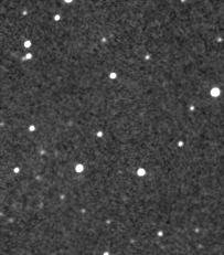
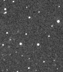
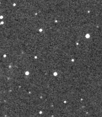
You to start by pointing two stars of the field in the first image:
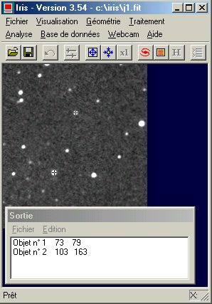
Then you make:
RREGISTER I J 30 3
This stage you can for example add the three images with the registered sequence:
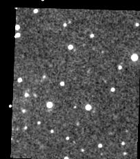
ADD2 J 3
Here the result:
Remark: to point another set of two stars you must unselect the Select objects command of the Analyse menu, then re-select it.
Command RREGISTER generates two text files in the working directory: the file SHIFT.LST which contains the geometrical parameters in translation of the transformation of the images (identical to file SHIFT.LST produced by REGISTER) and the file ROT.LST which contains the parameters in rotation of the transformation (the position of the pivot in X and Y, then the swing angle in degree compared to the first image of the sequence). Here contents of these files in the case of our example:
SHIFT.LST file
0.000 0.000
5.160 -11.862
17.969
-7.818
ROT.LST file
72.472 79.068 0.000
72.472 79.068
1.498
72.472 79.068 2.189
These files can beings used by command FILE_TRANS and new command FILE_ROT (syntax identical to FILE_TRANS) for re-run the geometrical transformation. For that you must carry out in first FILE_TRANS, then FILE_ROT. In our example, once command RREGISTER carried out first, the registration of the three images can be obtained by doing something like:
FILE_TRANS I J 3
FILE_ROT J J 3
Commands FILE_TRANS and FILE_ROT are particularly important when one wishes registrer the components of a trichromy image in the same way.
Command SETSPLINE
Syntax: SETSPLINE [MODE]
If you carry out command SETSPLINE 0 all operations of registrations run since the line of commands use the bilinear interpolation to calculate the registered images. If you carry out command SETSPLINE 1 same the operations use the spline interpolation method. The advantage of the spine interpolation spline is a less smooth of the images and thus a better preserved details. On the other hand the calculating time is longer. The commands concerned are for example REGISTER, PREGISTER, CREGISTER, RREGISTER. For the simple translation or the simple rotation of the image in memory you can use commands STRANS and SROT to profit from the spline interpolation spline (symmetrical functions the TRANS one and ROT which use they a bilinear interpolation). The profit of the spline mode is particularly visible in deep sky imagery.
The interpolation spline was already present in the preceding version of IRIS, but only for the accessible commands since the menus (for example the command Registration of stellar images... of Processing menu).
The dialog box Mosaic (Mosaic command... of Geometry menu) is enriched by a button Save image 2. The click on this button replace the image number 2 by its own image, but translated by current values DX and DY.
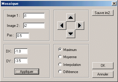
This option is very practical to centre
manually and interactively images (for stacking for example). with
The procedure is simple. Image 1 is always the first image of the sequence (I1 for example). One gives like value to the parameter Image 2 the second images of the sequence (I2). While acting on the direction buttons and by adjusting the step value of displacement it is then possible to superimpose precisely the two images (I2 relative to I1). Use the Difference option for better judging result. Then save the new centered image I2 while click on Save im2. You can start again for the image I3 and so on. You can then composite the images of the sequence I1, I2, I3... In.
Command FIND_HOT
The command makes it possible to generate a file lists (format text) in the working directory which contains the co-ordinates of the pixels which have an intensity higher than only one provided by the user.
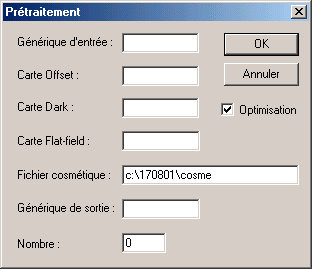
This file, known as cosmetic file, is then used by IRIS to correct certain systematic defects during the preprocessing of the deep-sky images. Thus, if command FIND_HOT applies to an image of the dark signal , the produced file will contain co-ordinates of the pixels of affected by an abnormally high dark current (hot pixels). When this file is read by a function of preprocessing, the pixels in questions in then treated images are replaced by a computed value starting from the intensity of the close pixels.
The syntax of the command is the following one:
FIND_HOT [LIST FILE] [THRESHOLD]
avec :
with:
[LIST FILE] the name of the file lists produced.
The name is supplemented by extension .LST.
[THRESHOLD] the
threshold for the discrimination of the hot points.
To note that IRIS turns over in the console the number of hot points found. For a normal CCD it is necessary to be arranged to adjust the threshold so as not to find much more than one ten hot points.
For example:
LOAD DARK
FIND_HOT COSME 300
Here a typical contents of the produced file (file COSME.LST in the example):
P 1086 1
P 402 7
P 1434 13
P 403 23
P 1372 27
C 468 0
The letter P indicates that it is necessary
to correct only one pixel of the image. The co-ordinates of the
first sick pixel is (1086, 1). Second is at the co-ordinates (402,
7) and so on.
The last line starts with C and was added manually to the file (for example with an editor like WordPad). It indicates to IRIS that it will be necessary during the pretreatment to replace the column of row 468 (on the basis of the left) by the average value of the adjacent columns.
In the present case the action of the last line of file COSME.LST is equivalent making:
REPAIRX 468
If the cosmetic file contains the line:
L 34 0
That means that it is necessary to replace the line of co-ordinates 34 (starting from the bottom of the image) by the value of the adjacent lines. To note that in the case of the correction of the lines and the columns the third value in a line of the cosmetic file must have a null value.
To apply the cosmetic corrections registered in the file lists you can use commands COSME and COSME2. Some dialog boxes can now also take into account information of a cosmetic file. For example (to notice that one indicated to IRIS where is located the cosmetic file because its directory is not the working directory):
Command DATA2PIC
Syntax: DATA2PIC
[DATA FILE NAME]
Converted a
text ASCII file with two columns into an image whose axis Y contains
the values (standardized to 32767) contained in the second column
of the file. This command is useful to import in IRIS spectral data.
Command DATA_BIN
Syntax : DATA_BIN [IN] [OUT] [BINNING FACTOR]
Carry out the binning of a data file, for example a file resulting from the photometric analysis, in order to increase the signal to noise ration. [ BINNING FACTOR ] is the factor of binning (typicaly value: 2 to 4).
Command DATA_REJECT
Syntax: DATA_REJECT
[IN] [OUT] [COEF]
Analyze a data file (file DELTA.DAT coming from the automatic photometric analysis for example) and eliminates the points deviating of more than [COEF]. sigma of the average value (sigma is the standard deviation of the distribution). [ IN ] is the name of the input file (it must have extension DAT on the disc). [OUT] is the name of the output text file.
Command DATA_RESAMPLE
Syntax: DATA_RESAMPLE
[IN] [OUT] [STEP]
Re-sampling
points of a data file (use of the spline interpolation). Useful
command for example to represent data spectral or an intensity distribution
curve with a integer step.
Command DATA_STAT
Syntax: DATA_STAT
[DATA FILE]
Turn over statistical data on the data file
[ DATA_FILE ].
Command
NGAIN3
Syntax: NGAIN3 [IN] [OUT] [NORM] [NUMBER]
Normalization of a sequence of images. For the difference of NGAIN2 it is necessary to define with the mouse the zone of the image in which the calculation is carried out.
Command PIC2DATA
Syntax: PIC2DATA [DATA FILE NAME]
Convert the values of the first line of the image in memory into a text file of name [DATA FILE NAME]. This command is particularly useful for the analysis of the spectral data starting from a spreadsheet or a program of display of curves.
And also an improved version of the command NUMBER. Suppose the sequence M57-1, M57-2, M57-3. The command NUMBER M57- return the number of images in the sequence (3) but mid-date of the acquisition.
